1.Installing packings
1-1: U-Packings, etc.
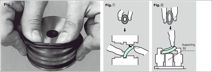
- On a piston, hook one side on the groove and push the packing by extending to the opposite side. (See Fig. ⑥)
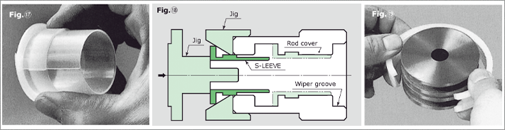
- Deform a rod packing to ellipse shape and slide its one side into the groove. Then insert the whole part from the opposite side by pushing the packing with your finger. Use a jig to install Small packing into a groove. (See Fig.⑦ and ⑧)
1-2: ST, STK-Seals
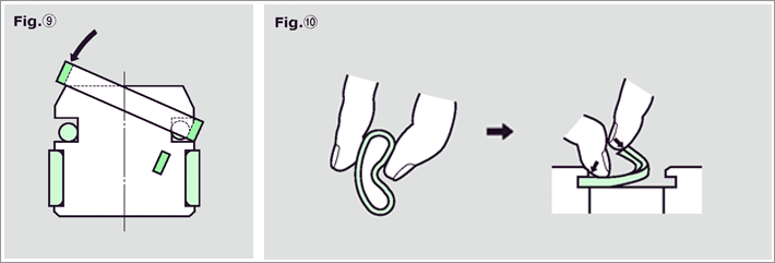
- Insert a back ring (rubber O-ring/Square ring) first, then hook one side of the seal ring on the groove and push the opposite side from the tapered side. (See Fig.⑨)
1-3: PG-Rings
- For a piston, hook one side of a ring and push the opposite side into the groove.
- For a rod, deform a ring into the shape in Fig. ⑩, insert one side and push the whole part by holding the ring with your finger. (See Fig.⑩)
1-4: SMJ-Seals
- Insert a back ring (O-ring made of rubber) first, then deform the seal ring into the shape in Fig. ⑩, insert one side and push the whole part by holding the ring with your finger.
In this time, note that a seal ring has the correct direction to be inserted.
Try to minimize deformation of the seal ring during installation. (See Fig. ⑩)
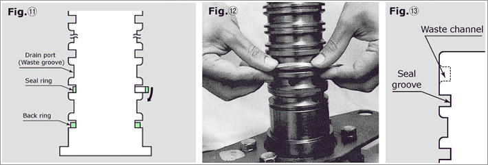
1-5: Rotary joint
- When installing STK(STR)-Seal, the procedures are:
①Install just one back ring (square ring made of rubber) in the seal groove located at the bottom.
②Move a seal ring downward through other seal grooves and drain ports. (See Fig. ⑪)
③When installing a seal ring in the seal groove, hook one side of the seal ring in the groove and quickly push over to the opposite side sliding on R chamfered or tapered part. (See Fig. ⑫)
④Installation of seal rings to the second and subsequent grooves from the bottom, repeat the procedures ① to ③ .
- Also, note the following points.
①Do not install more than one back ring at the same time.nstall seal ring and back ring in pair for an easiest nstallation.
②When designing the structure, consider the smooth installation of the seal rings by R chamfering (R2 to 3) on the edges of drain ports and place groove interval narrow.
③When an interval from the end to the groove is distant, place a waste channel to help the installation of a seal ring easier. (See Fig.⑬)
④Set the depth of drain ports in the same plane with the seal grooves so that the drain ports are used as waste channels to slide seal rings.
2.Installing Dust seals
- Install SDR, SER, SFR and SCK-Wipers in the same manner as the installation of rod packings. (See Fig. ⑦ and ⑧ in page 17.)
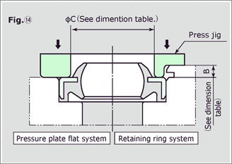
- When installing a SCK-Wiper, apply enough grease(Materialsto the inside of the groove.Consider a rust control treatment on the surface of inner circumference of pressure plate surface((φC size at page 58).h
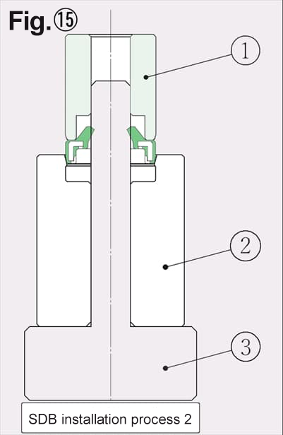
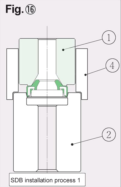
- Press in SCB and SDB-Wipers by use of a jig to avoid inclination. (See Fig. ⑭ and ⑮ and ⑯)
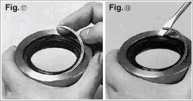
- Retaining rings for SCB and SDB-Wipers are available in our product lines. Retaining rings for SCB and SDB-Wipers allow easy installation and removal without using any special jig. (See Fig. ⑰ and ⑱)
(Installation process)
- Insert SDB inner peripheral guide③ into rod cover (housing)②.
- Install SDB-Wiper to SDB inner peripheral guide③ ~Push SDB-Wiper softly into the rod cover.
- Install pushing zig① into SDB inner peripheral guide③ .
- Push pushing zig① by hand press for press-in.
- Remove pushing zig① and then SDB inner peripheral guide③ from the rod cover.
(Installation process)
- Push SDB-Wiper softly into rod cover (housing)②.
- Place pushing zig① and pushing zig guide④ onto the shoulder of SDB-Wiper.
- Push pushing zig① by hand press for press-in.
- Remove pushing zig① and pushing zig guide④ .
3.Installing Bearings
- Install a S-LEEVE prior to installing a packing or a wiper.
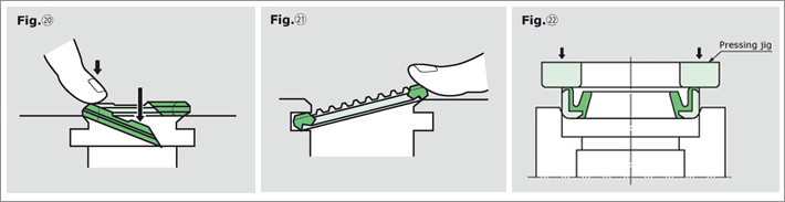
- ロッド用のエスリーブでφ45以上は、指でエスリーブを変形させ、ダストシール側から挿入してください。(図⑲参照)
- ロッド用でφ40以下のエスリーブは装着治具により、圧力側から挿入してください。(図⑳参照)
- ピストン用のエスリーブおよびウェアリングは円周上一か所カットされておりますので、ひろげて装着してください。(図㉑参照)
- Install a PWL-Bearing after all other packings are mounted on.
- Try to minimize deformation during the installing process.
4.Installing Cushion seals
- KCSクッションシールはカット部の一端を軸方向にずらしてみぞにひっかけ円周方向に沿ってすばやく押し込みます。(図㉒参照)
Minimize deformation during the installing process.
- YCSクッションシールはロッドパッキンと同様に楕円状に変形させながらみぞに入れてゆき、最後に残った部分の中央を図のように指で速やかに押し込みます。(図㉓参照)
Minimize deformation during the installing process.
- PCSクッションシールは治具を用い、傾かないように圧入してください。(図㉔参照)